
Stamped Electrical Terminals
Before Plating Batch: Stamped Electrical Terminals Finish Audit Checklist
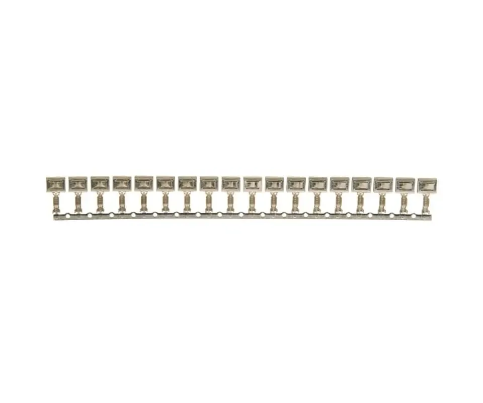
Table of Contents
A reel of terminals passes the visual inspection and the go/no-go gauge. Six months later, tin whiskers bridge the 0.5 mm contact gap on your PCB — and the field return analysis traces back to a skipped JESD201 anneal.
Key Takeaways
- JESD201 anneal mandate: Post-plating annealing at 150°C within 24 hours of tin plating is the single most skipped step — and the root cause of field-level tin whisker failures.
- XRF mapping depth: A supplier who measures plating thickness at one spot per reel is not testing — demand three-zone XRF mapping across contact, bend, and crimp areas.
- Plating adhesion test: Tape test per ASTM D3359 is a pass-through screen; demand a bend test on the actual terminal geometry to catch hydrogen embrittlement before it reaches the field.
In this checklist, you will verify plating material specifications, pre-treatment cleanliness protocols, post-plating anneal compliance, and thickness verification methods before the plating batch runs.
Go through every item before the batch runs.
Plating Specification
- Confirm the plating material — tin, gold, silver, nickel, or palladium — is specified with minimum thickness in microns on the terminal drawing.
- Verify the coverage zone is defined with a clear boundary: full-strip plating, selective reel-to-reel stripe, or spot plating on the contact zone only.
- Audit that the plating thickness specification differentiates between the contact zone, the bend radius, and the crimp barrel — one value for all three is insufficient.
- Confirm the underplate layer — nickel or copper flash — is specified with its own thickness tolerance, not bundled into the top coat figure.
- Validate that the tin plating specification references JESD201 for whisker mitigation or an equivalent industry standard.
- Check that gold plating over nickel is specified with a minimum gold thickness of 0.8 µm for industrial connectors per MIL-DTL-45204.
- Review the plating adhesion requirement — confirm a bend test or thermal shock test is specified, not just a tape test.
[Gate Condition]: Do not proceed to pre-treatment until the plating material, thickness per zone, underplate specification, and adhesion test method are documented and approved on the terminal drawing.
Pre-Treatment
- Confirm the cleaning process — alkaline degreasing, electrolytic cleaning, or acid activation — is specified before plating and documented in the process sheet.
- Verify that the cleaning bath concentration, temperature, and immersion time are controlled within documented ranges with periodic titration records available.
- Audit the rinse water quality specification to confirm deionized water with conductivity below 10 µS/cm is used between process tanks.
- Check that the terminals are plated within 4 hours of cleaning — any longer and surface oxidation compromises adhesion on copper alloys.
- Confirm the activation step — typically a mild acid dip — immediately precedes the plating bath entry with no intermediate drying step.
- Validate that the racking or barrel loading method prevents terminal-to-terminal contact during immersion to ensure uniform current density distribution.
[Gate Condition]: Do not proceed to plating until the cleaning protocol, rinse water quality, and maximum time-to-plate window are documented and signed off by the process engineering team.
Post-Plating Verification
- Confirm that the supplier performs JESD201-compliant post-plating annealing at 150°C within 24 hours of tin plating — demand the furnace chart record.
- Verify XRF plating thickness is measured at three zones per strip — the contact area, the bend radius, and the crimp barrel — with results recorded per reel.
- Audit the plating adhesion test method to confirm a 90-degree bend test on actual terminal geometry, not a flat coupon, is performed per production lot.
- Check that the stamped electrical terminals post-plating inspection includes a 10× magnification visual check for blistering, pitting, or nodular deposits.
- Validate that the supplier performs cross-section metallography at a minimum frequency of once per shift to verify plating thickness and underplate integrity.
- Confirm that the salt spray test duration — typically 24 to 96 hours per ASTM B117 — is specified and that the acceptance criteria are defined in the control plan.
- Review the packaging specification to confirm that plated terminals are separated by interleaving material to prevent contact abrasion during shipping.
[Gate Condition]: Do not approve the plating batch until the XRF thickness map, furnace anneal chart, adhesion bend test report, and cross-section micrograph are reviewed and filed per lot.
Audit to PO
Plated terminals passing incoming gauge can fail field-level contact resistance because bend radius XRF thickness went unverified. Kravzik runs every plating batch through a documented verification sequence — pre-treatment logs, current density monitoring, JESD201 anneal records, and three-zone XRF mapping — with all data shipping alongside your PPAP package.
Send us your terminal drawing for a complete finish audit with thickness mapping protocol and JESD201 compliance verification, delivered within 48 hours.
NEXT STEP
Ready to Manufacture Your Part?
Send us your drawing or sample — our engineers return DFM feedback within 24 hours with pricing and lead time from our IATF 16949 factory.
Written by
Ray Chan
Manufacturing engineer at KRAVZIK (Dongguan Guohong Precision). Writes shop-floor guides on progressive-die stamping, injection molding and precision component sourcing for global OEM buyers.