
IATF 16949 Certified Manufacturer
How to Control Springback in High-Strength Automotive Brackets
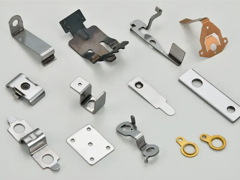
Table of Contents
A mounting bracket stamped from 1.2 mm 65Mn spring steel came off the die with 3.8 degrees of springback. The 10 mm mounting hole sat 1.7 mm off the rail hole on the body panel. Forty assemblies per hour were pulled for rework, and the line fell two shifts behind before the die was pulled.
Key Takeaways
- Machine dies to compensate for elastic recovery using predicted CAE simulation data.
- Use overbending and coining strategies to force permanent plastic deformation in AHSS.
- Validate physical parts using 3D scanning to ensure mass production dimensional stability.
The bracket failed the flush and gap check before it reached the torque station. The fix took three tryout iterations and a die revision. Every one of those costs was avoidable, because springback is predictable.
Springback is the elastic recovery that follows every bend. It shows up as a gap, a misaligned hole, or a twisted flange, and it is expensive to chase after tooling is cut. This guide covers the physics, the variables, the compensation methods, and the measurement loop that keep automotive brackets inside tolerance.
The Snapshot
- Thin-sheet brackets typically spring back 2-8 degrees after forming, depending on material, thickness, and bend radius.
- Springback rises nearly in proportion to the bend ratio r/t. A 3 mm radius on 1.2 mm sheet returns about 3 times the angle of a 1 mm radius.
- Overbend compensation of 0.5-3 degrees covers most bracket geometries, while bottoming cuts recovery below 0.5 degrees at 5-10 times the air-bend tonnage.
- Bracket-class tolerances run ±0.05-0.1 mm (typical), and a stable process holds Cpk at 1.67 or higher with gage repeatability and reproducibility (GRR) below 10 percent.
The Physics of Springback in a Bent Bracket
Bending puts the outer surface of the sheet in tension and the inner surface in compression. Between them sits the neutral axis, the plane where stress is zero. When the punch retracts, the elastically strained part of the bend recovers, and the flange springs open. That angular recovery is springback, and it is never zero.
The neutral axis does not stay at mid-thickness. It shifts toward the compression side during forming, which is why bend allowance calculations use a k-factor. For tight radii in automotive brackets, k-factors of 0.3-0.5 are typical. The shift also means the outer fibers carry most of the permanent set.
The bend ratio r/t is the geometric master variable. A standard first-order estimate puts the recovery angle at about 3 times the yield-to-modulus ratio times r/t, applied to the bend angle. For 65Mn and C75S with yield strength typically 600-1000 MPa and a modulus near 200 GPa, the ratio lands around 0.003-0.005. A 90 degree bend at r/t of 1 then returns about 1 degree before any compensation.
That is why hardened spring steel returns far more than mild steel. Mild steel yields near 200-350 MPa, so the same geometry returns roughly 0.5-2 degrees, while spring steel pushes toward the 2-8 degree band. Thickness matters for the same reason, because it changes r/t for a fixed tool radius.
Variables That Drive the Springback Angle
Five variables decide how much a bracket returns after forming. Material strength sets the elastic energy stored in the bend zone. Thickness and bend radius set r/t. The bend angle scales the absolute recovery. Tooling geometry, mainly the die opening, decides how localized the bend is. Table 1 summarizes the typical effect of each.
| Variable | Change | Typical effect on springback. |
|---|---|---|
| Yield strength | 600 to 1000 MPa | Recovery rises nearly in proportion, from roughly 1 degree toward 2-3 degrees on a 90 degree bend. |
| Sheet thickness | 0.8 to 2.0 mm | Lowers r/t and holds the bend; angular recovery drops. |
| Bend radius, r/t | 0.5 to 3 | Springback rises in near proportion to r/t. |
| Bend angle | 45 to 120 degrees | Absolute recovery grows with angle; the percentage stays near constant. |
| Die opening width | Wide to narrow | Narrower openings localize the bend and reduce recovery. |
Values are typical for thin-sheet air bending of spring steel; verify on first articles for the exact geometry.
Material lots add the real-world spread. A coil at the top of the 735-1180 MPa tensile range can return close to 60 percent more angle than one at the bottom. Recovery scales with yield strength, and coil thickness drift moves r/t the same way. Compensation must therefore be set against the actual production lot, not the material certificate alone.
Prediction and Compensation Methods
Compensation works by forming the part past its target so that recovery lands on the print. Three methods dominate automotive bracket tooling: overbend, bottoming, and die compensation. Table 2 compares them.
| Method | How it works | Typical result. |
|---|---|---|
| Overbend | Punch angle set past target; part recovers to the print angle | 0.5-3 degrees of correction; needs stable material lots. |
| Bottoming, coining | Sheet pressed flat at bottom of stroke at 5-10 times air-bend tonnage | Recovery often below 0.5 degrees; faster tool wear. |
| Die compensation | Punch radius and angle revised from tryout data | Usually lands within tolerance in 1-2 iterations. |
| Rib and embossment | Stiffened flange resists elastic recovery | Measurably less angular recovery; add at the design stage. |
Values are typical for automotive brackets on 25-300 ton presses; confirm each method with trial forming.
Overbend is the fastest fix. Form 0.5-3 degrees past the target, measure the recovery, and close the loop on the punch angle. Bottoming is the strongest fix. Pressing the sheet flat at the bottom of the stroke at 5-10 times the air-bend force pushes recovery below 0.5 degrees. It costs tool wear, so it suits high-volume features where the press has headroom in the 25-300 ton range.
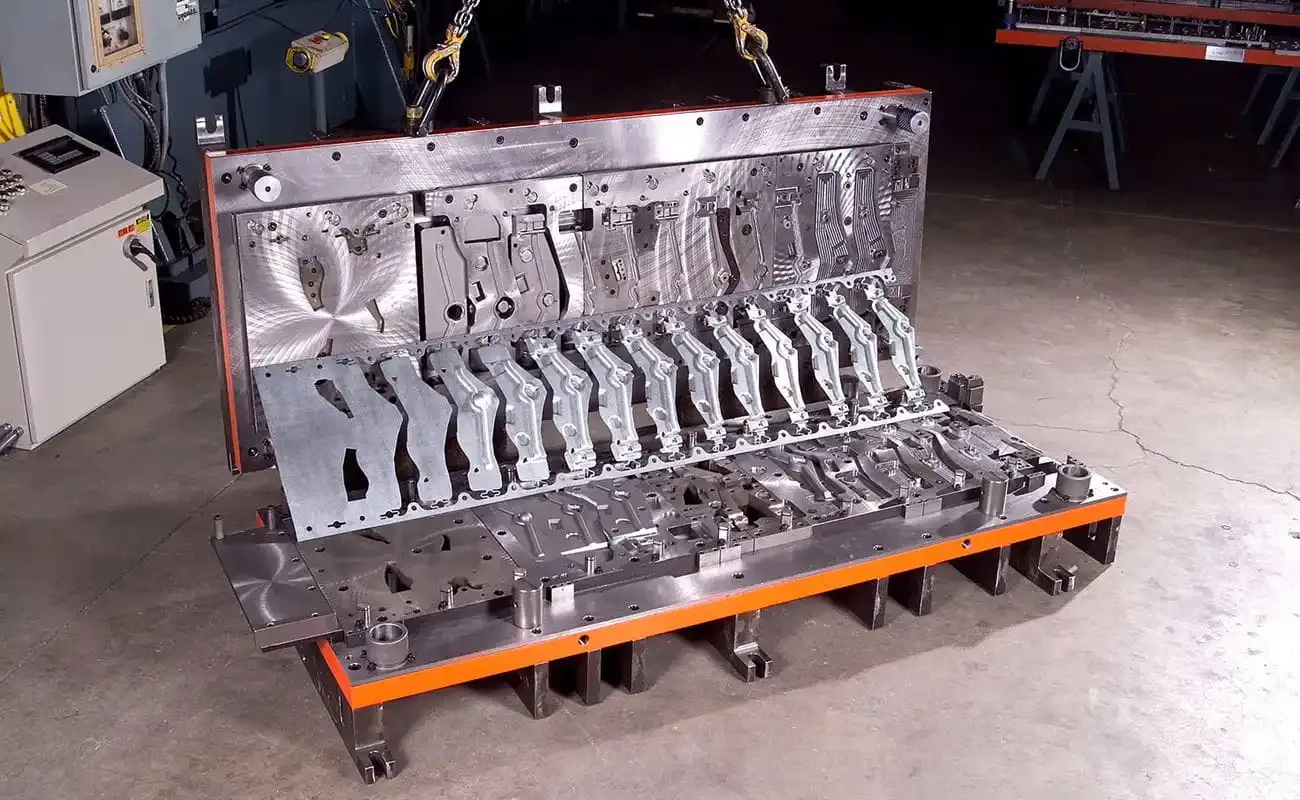
Die compensation handles geometry that overbend cannot, such as curled flanges or compound bends. The tryout data sets the revised punch radius and angle, usually within 1-2 iterations. On progressive dies running up to 800 SPM, adjustable inserts can fine-tune the bend angle in minutes instead of re-cutting the punch.
Tolerance Control for Bracket-Class Parts
A 3 degree recovery on a 50 mm flange moves the flange tip about 2.6 mm. No bracket absorbs that without compensation, which is why bracket-class tolerances sit at ±0.05-0.1 mm (typical) on functional features. The control strategy is simple in concept: compensation sets the mean, and process discipline sets the spread.
On our stamping lines, key dimensions are held to ±0.005 mm where the print demands it. Cpk of 1.67 or higher is the release gate, which equals a five-sigma process at about 0.6 ppm defective parts per characteristic. Measurement systems are qualified with GRR below 10 percent of the tolerance band, following the AIAG guidance used under IATF 16949. A bracket at ±0.05-0.1 mm sits well inside that capability once springback is compensated.
Process discipline covers the inputs that move springback. Coil tensile band, thickness tolerance, and press tonnage repeatability all shift the recovery angle. When a new coil lot enters production, the bend angle is re-verified before the run. SPC charts track hole position and flange angle on every lot.
Verification and Measurement
Compensation is only as good as the measurement loop that feeds it. Three tools cover most bracket programs: check fixtures for high-volume pass-fail, CMM for full geometry, and inline optical systems for drift detection.
| Method | What it verifies | Typical performance. |
|---|---|---|
| Check fixture, hard gage | Hole position, flush and gap at mating surfaces | Pass-fail in seconds; GRR below 10 percent of tolerance. |
| CMM, coordinate measuring machine | Full 3D profile, hole patterns, flange angles | Measurement uncertainty below 0.01 mm. |
| Inline optical system | Critical features on progressive lines up to 800 SPM | Flags drift between scheduled checks. |
Performance figures are typical for shop-floor gaging; verify uncertainty against the tolerance band.
First articles get the full treatment: CMM layout, angle measurement on every bend, and comparison against the compensation model. Production relies on the check fixture, with CMM audits on a schedule. If a feature drifts past a control limit set at half the tolerance band, the die insert is adjusted before the process can build scrap.
GRR below 10 percent is re-verified whenever a new fixture or operator setup is introduced. Cpk of 1.67 or higher is the release gate for every production lot.
Design Rules to Avoid Springback
The cheapest springback control happens before the die is cut. Six design rules catch most problems at the drawing stage.
- Keep r/t between 1 and 2 for spring steel. Hardened 65Mn and C75S typically need a minimum bend radius of 2-4 times sheet thickness; sharper radii risk cracking, wider ones invite springback.
- Add a rib, embossment, or hem near the bend line. Stiffened sections recover less than flat flanges.
- Keep bends symmetric about the part centerline. Asymmetric bends twist the bracket during recovery.
- Orient the bend axis across the rolling direction where possible. Bends parallel to the grain crack more easily and recover less consistently.
- Call out realistic tolerances. Use ±0.05-0.1 mm on functional features and looser values on cosmetic ones; tightening everything multiplies inspection cost.
- Build the bend allowance into the flat pattern. A k-factor of 0.3-0.5 (typical) keeps hole positions true after forming.
Coating deserves one note. Galvanizing and electrophoretic coating are applied after forming, so they do not change springback. Qualify dimensions on coated parts anyway, because a layer of tens of microns (typical) can affect a press-fit or clip engagement.
The Bottom Line
Springback in automotive brackets is predictable once you control the inputs. Yield strength, thickness, and r/t set the recovery angle. Overbend, bottoming, and die compensation put the process mean on target. Check fixtures and CMM audits keep it there, with Cpk of 1.67 or higher and GRR below 10 percent.
Review the geometry at the drawing stage, and treat first tooling trials as a measurement exercise, not a guessing game. For the production side of bracket stamping, see our stamping services overview. If material selection is still open, the spring steel materials page covers 65Mn and C75S in detail, and related articles live in the blog.
NEXT STEP
Ready to Manufacture Your Part?
Send us your drawing or sample — our engineers return DFM feedback within 24 hours with pricing and lead time from our IATF 16949 factory.
Written by
Ray Chan
Manufacturing engineer at KRAVZIK (Dongguan Guohong Precision). Writes shop-floor guides on progressive-die stamping, injection molding and precision component sourcing for global OEM buyers.