
Engineering Guide
Automotive Brackets: The Complete Guide to Stamped Bracket Design and Manufacturing
Table of Contents
A stamped seat bracket came off the die with a 2.4 degree springback error on its main flange. The 12 mm mounting hole sat 1.6 mm off the floor-panel hole. The assembly line pulled 400 parts an hour for rework, and the program lost two shifts before the die was pulled. Every one of those costs was avoidable, because bracket springback is predictable and compensable.
Automotive brackets look like simple parts. A flat plate, two flanges, a few holes. In an assembled vehicle, that small bracket carries the position of everything bolted to it. A hole 0.1mm off target shifts the sensor, the seat or the module it mounts.
This guide covers stamped automotive brackets end to end: bracket types, materials, processes, tolerance control, springback, plating, cost drivers and quality systems. It is written for engineers and buyers evaluating automotive bracket stamping services, with production numbers instead of marketing language.
The Snapshot
- Progressive die stamping runs automotive brackets on 25 to 300 ton presses at up to 800 SPM
- Functional bracket features typically hold ±0.05 to 0.1mm, with critical dimensions at ±0.005mm and Cpk of 1.67 or higher
- SPCC, SECC, SUS301 and 65Mn steels cover most structural brackets, while aluminum and copper alloys serve weight, thermal and current-carrying roles
- Above roughly 50,000 parts per year, stamping beats machining and fabrication on unit cost by 3 to 10 times
- Progressive die tooling costs USD 20k to 200k and takes 4 to 6 weeks from an in-house toolroom
What Are Automotive Brackets?
An automotive bracket is a stamped component that locates, mounts or supports another part. Brackets bolt, weld or clip onto body, chassis, engine and drivetrain structures. They hold sensors, cameras, seats, hoses, harnesses, batteries and electronics.
Brackets are bending-heavy parts. A typical design is a flat plate with flanges, holes and mounting faces. The forming work concentrates in the bends, which makes springback the dominant quality risk.
Stamping dominates bracket production for three reasons: speed, consistency and cost per part. A progressive die produces one finished bracket on every press stroke. The process repeats the same geometry millions of times without operator input.
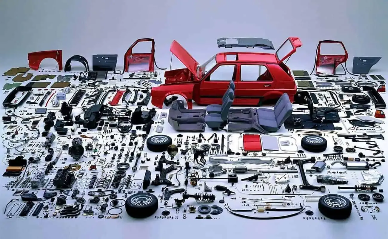
A single mid-size vehicle carries hundreds of stamped brackets, from visible structural parts to hidden harness clips. The count grows with electronics content, because every sensor and camera module needs its own mounting bracket. Electric vehicles add battery-pack frames and busbar mounting brackets on top of that.
Types of Automotive Brackets
Bracket programs split into three engineering classes: structural, mounting and functional. Each class sets different tolerances, materials and verification methods.
Structural brackets carry load and must survive fatigue. Seat brackets, airbag brackets and chassis reinforcements fall here. They use SPCC or SUS301 and are validated with fatigue tests, not just dimensional checks.
Mounting brackets position a component against the body or powertrain. Alternator and sensor brackets fall here. Hole position is the critical dimension, because a misaligned hole shifts the whole assembly.
Functional brackets combine structure with a job. Spring clips, harness retainers and heat-sink brackets fall here. They use spring steel or aluminum and hold a spring rate or a thermal path.
| Bracket class | Examples | Typical material | Release gate |
|---|---|---|---|
| Structural | Seat, airbag, chassis brackets | SPCC, SUS301 | Fatigue test, hole position |
| Mounting | Alternator, sensor, camera brackets | SPCC, AL5052 | Hole position, flush and gap |
| Functional | Spring clips, harness retainers | 65Mn, SUS301 | Spring rate, retention force |
| Thermal and electrical | Heat-sink brackets, busbar mounts | AL6061, C1100 | Thermal conductivity, current capacity |
Classes overlap in practice; assign the bracket to the class with the tightest requirement.
Electrification shifts the bracket mix. An EV adds battery-pack frames, busbar mounting brackets and thermal brackets for power electronics. These parts carry current and thermal duty, so copper and aluminum programs grow against traditional steel brackets.
The bracket family also includes antenna mounts, exhaust hangers and pedal brackets. What unites them is geometry: a stamped sheet with bends, holes and mounting faces. Once the geometry fits that shape, the same die logic applies across the whole family.
Stamping vs Machining and Fabrication
Machining cuts a bracket from solid stock. Fabrication cuts and welds pieces together. Stamping forms the part from sheet in one continuous process. The choice is economic before it is technical.
The crossover point is around 50,000 parts per year. Below that volume, machining or laser-cut fabrication can win on tooling cost. Above it, stamping unit cost falls 3 to 10 times below machined equivalents, because the die work is amortized over millions of strokes.
Stamping also wins on consistency. A die repeats the same geometry on every stroke, so part-to-part variation comes from material and press, not from the operator. Machined brackets drift with tool wear and setup, and welded assemblies drift with every joint.
Welded fabrication adds another risk. Each weld is a tolerance event. Heat distortion moves holes, and bracket assemblies need straightening and rework. A stamped one-piece bracket has no weld joints and no distortion.
Casting and Forging at Volume
Casting and forging also compete at volume. Cast brackets suit complex shapes but add wall-thickness variation and porosity risk. Forged brackets offer higher strength at a higher part cost. Stamping wins when the design is a plate with flanges, which is most brackets.
| Process | Typical bracket volume | Unit cost trend | Main risk |
|---|---|---|---|
| Progressive die stamping | 50k to 500M parts per year | 3 to 10 times lower above 50k | Tooling lead time, springback |
| CNC machining | Under 50k parts per year | Flat, material-heavy | Material waste, cycle time |
| Fabrication and welding | Low volume, large brackets | Labor-heavy | Weld distortion, tolerance stack |
Volume bands are typical; the crossover shifts with part size and material cost.
Materials for Stamped Automotive Brackets
Material choice drives strength, tolerance and price. Steel dominates structural brackets. Aluminum serves weight and thermal duty. Copper alloys appear where brackets carry current.
Steel for Structural Brackets
| Grade | Tensile strength | Tolerance band | Typical use |
|---|---|---|---|
| SPCC cold-rolled | 280 to 400 MPa | ±0.03mm | Brackets, covers |
| SECC galvanized | 270 to 380 MPa | ±0.03mm | Shields, chassis parts |
| SUS301 stainless | 520 to 1,200 MPa | ±0.02mm | Springs, structural clips |
| 65Mn spring steel | 735 to 1,180 MPa | ±0.02mm | Clips, retaining rings |
Strength bands are typical mill ranges; tolerance bands are typical stamping capability for bracket-class features.
Spring steel returns more springback than mild steel, but it holds a clip or a retainer without a separate spring. Galvanized SECC brings corrosion resistance to exposed chassis brackets.
Aluminum for Lightweight and Thermal Brackets
| Grade | Thermal conductivity | Tolerance band | Typical use |
|---|---|---|---|
| AL1060 | 234 W/m·K | ±0.04mm | Heat sinks, cooling plates |
| AL5052 | 138 W/m·K | ±0.03mm | Housings, shields |
| AL6061 | 167 W/m·K | ±0.03mm | Structural, anodized parts |
Thermal values are typical datasheet figures at room temperature.
Aluminum brackets cut mass on EV battery frames and thermal brackets on power electronics. AL5052 forms well and resists corrosion. AL6061 accepts anodizing for wear and appearance.
Copper Alloys for Current-Carrying Brackets
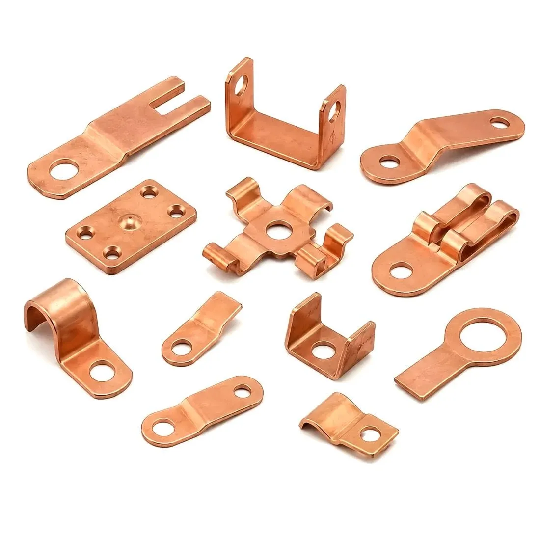
Busbar brackets and battery connection brackets carry current, not just load. C1100 ETP copper conducts at 101% IACS and dominates high-current parts. C1720 beryllium copper at 22% IACS serves spring contacts. C5210 phosphor bronze at 15% IACS covers fatigue-rated terminals.
Plating is part of the material system. Tin, silver, gold or nickel can be applied selectively. The burr direction is designed away from the plating surface at the die stage.
Material control matters at scale. Same-lot coils, incoming chemistry verification and trace codes per batch keep the process stable. A coil at the top of a tensile band can shift springback by 50% or more, so the stamping lot must match the die compensation.
Stamping Processes for Automotive Brackets
Four processes produce automotive brackets. Progressive die stamping dominates the family. Transfer and fine blanking cover larger or sheared-edge parts. High-speed lines handle small functional brackets.
| Process | How it works | Typical bracket use | Typical speed |
|---|---|---|---|
| Progressive die | Coil feeds through a multi-station die, one part per stroke | Mounting and structural brackets | 200 to 800 SPM |
| Transfer die | Blank moves between separate stations | Large or deep-formed brackets | 30 to 120 SPM |
| High-speed stamping | Ultra-rigid press, thin stock | Clips, retainers, small functional parts | 600 to 1,200 SPM |
| Fine blanking | Triple-action press, full shear edge | Precision plates, latch parts | 10 to 60 SPM |
Speed ranges are typical for bracket-class tooling; the press fleet runs 25 to 300 tons.
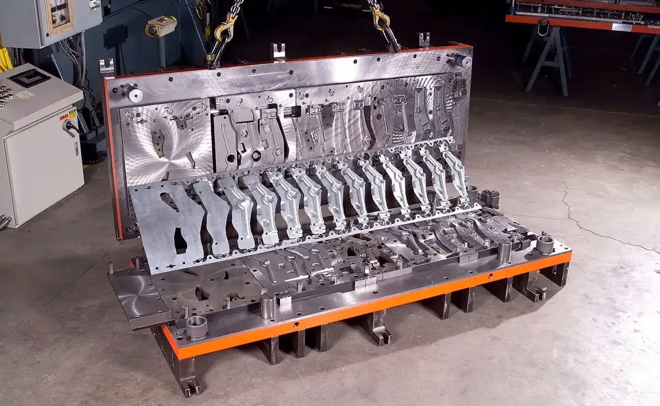
Progressive dies consolidate operations. Piercing, forming, coining and tapping happen in one die. The die holds datum relationships in one setup. A bracket with five holes and two flanges comes off the line finished, not as a blank for secondary work.
Two die details decide bracket quality: piloting and station order. Pilots hold strip position so every station registers against the same datum. Station order places tight features first and bends last, which keeps springback from moving pierced holes.
High-speed lines change the game for small functional brackets. Thin stock and micro features run at 600 to 1,200 SPM on ultra-rigid presses. The same die logic applies, but the press frame and feed accuracy carry more of the tolerance load.
Tolerance Capability for Bracket-Class Parts
Tolerance in bracket stamping is a system property. Press rigidity, die condition, material lot, temperature and measurement all set the achievable band. On critical dimensions, KRAVZIK holds ±0.005mm with CMM verification and capability studies at Cpk of 1.67 or higher.
Functional bracket features typically run looser, at ±0.05 to 0.1mm. Spending ±0.005mm only where the function lives keeps die cost and inspection cost under control.
Five variables set the tolerance band:
- Material thickness: 0.08mm foil forms to ±0.01mm, while 4.0mm plate runs to ±0.05mm
- Press rigidity: frame deflection under load shifts die alignment, below 0.01mm on rigid presses at 80% load
- Die wear: regrind intervals of 100k to 500k strokes keep edge condition stable
- Temperature: steel dies grow about 11 μm/m per 10°C, and toolrooms run at 20 ± 2°C
- Measurement: gauge GR&R must stay under 10% of the tolerance band, or the capability data is measurement noise
Cpk of 1.67 equals a five-sigma process at about 0.6 defective parts per million per characteristic. That is the release gate for critical dimensions. Bracket-class features at ±0.05 to 0.1mm sit well inside it once the die is stable.
Ask the supplier for the GR&R study, not just the tolerance claim. A capability number without a measurement system behind it is a marketing number.
Verification follows a plan, not a mood. First articles get full CMM layout and angle checks on every bend. Production relies on check fixtures with CMM audits on a schedule. If a feature drifts past a control limit set at half the tolerance band, the die insert is adjusted before the process can build scrap.
Design for Stamping: Bracket DFM Rules
Small design choices decide whether a bracket runs at 800 SPM or fights the die. These rules matter most in automotive bracket programs:
| Design rule | Typical value | Why it matters |
|---|---|---|
| Minimum bend radius | 1x thickness for copper, 1.5x for steel and aluminum | Below this, outer fibers crack |
| Minimum hole diameter | 0.8x thickness, 0.3mm absolute | Pierce punch strength and slug clearance |
| Hole-to-edge distance | 1.5x thickness | Edge distortion and web tearing |
| Minimum feature size | 0.5mm stamped, 0.3mm fine blanked | Die construction limits |
| Tolerance callout | Critical dimensions only at ±0.005mm | Every tight tolerance adds a die station and an inspection point |
| Grain direction | Bend line perpendicular to coil grain | Parallel bends crack in hard materials |
Values are typical design rules for bracket-class stamping; confirm against the material datasheet.
The most expensive sentence on a bracket drawing is a tight tolerance on a non-critical dimension. Spend the tolerance budget where the function lives.
Add stiffening geometry early. A rib or embossment near the bend line reduces springback and stabilizes the flange. Design it in at the CAD stage, because a die revision later costs weeks.
Springback Control in Bracket Dies
Brackets are bending parts, so springback is the dominant quality risk. Metal springs back elastically after forming. The angle cut into the die is not the angle that comes out.
The bend ratio r/t is the master variable. A 3mm radius on 1.2mm sheet returns about three times the angle of a 1mm radius. Compensation values are material-specific:
| Material | Typical springback at a 90 degree bend | Compensation method |
|---|---|---|
| C1100 copper (soft) | 1 to 3 degrees | Overbend in die, coin the bend zone |
| C1720 beryllium copper | 3 to 6 degrees | Overbend plus stress-relief anneal |
| SUS301 stainless (hard) | 5 to 12 degrees | Overbend plus bottoming |
| AL5052 | 4 to 8 degrees | Overbend, iterate compensation |
| 65Mn spring steel | 8 to 15 degrees | Overbend plus coining, bend across grain |
Values are typical for a 90 degree air bend; verify on first articles for the exact geometry and lot.
Three methods dominate bracket dies. Overbend forms past the target by 0.5 to 3 degrees. Bottoming presses the sheet flat at the bottom of the stroke, cutting recovery below 0.5 degrees at 5 to 10 times air-bend tonnage. Die compensation revises punch radius and angle from tryout data, usually within 1 to 2 iterations.
Compensation is only as good as the measurement loop that feeds it. Check fixtures give pass-fail in seconds on hole position and flush. CMM audits cover full geometry, and inline optical systems flag drift on lines up to 800 SPM.
Die iteration speed decides program risk. The first article rarely matches the print on springy material. An in-house toolroom closes the loop in days, while an outsourced die can take months.
Plating and Surface Treatment for Brackets
Most automotive brackets are plated, galvanized or coated. The treatment is designed in at the die stage, not bolted on after forming.
| Treatment | Thickness range | Purpose | Typical use |
|---|---|---|---|
| Tin, selective or full | 1 to 8 μm | Solderability, corrosion barrier | Terminals, connector brackets |
| Silver | 1 to 5 μm | Low contact resistance at high current | EV battery connectors, busbar mounts |
| Gold | 0.1 to 1.5 μm | Oxidation-free signal contacts | Sensor and ADAS contacts |
| Nickel | 1 to 10 μm | Wear and diffusion barrier | High-temperature engine bay parts |
| Zinc or passivate | 5 to 15 μm | Corrosion protection | Steel brackets, clips |
Thickness ranges are typical; salt spray verification runs per ASTM B117, typically 48 to 72 hours for automotive parts.
Selective plating is the cost saver. Only the contact or mounting zone is plated, cutting silver and gold consumption by up to 90%. Burr direction is designed away from the plating surface at the die stage. A post-stamp plating defect is almost always a die design defect.
Zinc or passivate protects steel brackets from underbody corrosion. The coating is applied after forming, so it does not change springback. Qualify dimensions on coated parts anyway, because a layer of tens of microns can affect a press-fit or clip engagement.
Verification is numeric: plating thickness per IPC or ASTM methods, salt spray hours per ASTM B117, and adhesion testing after heat aging.
Cost Drivers for Stamped Brackets
Bracket cost breaks into four buckets, and three are decided before the first part exists.
| Cost driver | How it scales | Lever you control |
|---|---|---|
| Material | 30 to 60% of part cost, strip layout sets utilization | Nesting, coil width, gauge |
| Tooling | Progressive die USD 20k to 200k plus, amortized over volume | Committed volume, die design |
| Process | In-die operations remove secondary vendor cost | Die feature scope |
| Logistics | One integrated factory means one shipment and one owner | Supplier consolidation |
Shares and ranges are typical for automotive bracket programs; material share varies with grade and gauge.
The crossover curve is the same for every program. Below about 50,000 parts per year, machining or fabrication wins. Above it, stamping wins by 3 to 10 times on unit cost.
Volume commitment is the biggest price lever. A committed annual volume lets the supplier amortize the die and buy coil at better rates. Typical tooling lead times run 4 to 6 weeks, and first articles follow in days on a progressive line.
Watch the hidden costs too. Sorting after a tolerance drift, plating rework and line-side rejects all burn margin. A die you can iterate on quickly is the cheapest insurance against all three.
Automotive Quality Standards for Bracket Programs
Automotive bracket programs run inside IATF 16949. The quality system is a documentation pipeline, not a certificate on the wall.
| Element | What it proves | Typical requirement |
|---|---|---|
| IATF 16949 | Global automotive quality system in place | Certified facility |
| PPAP Level 3 | Process capable before production | DFMEA, PFMEA, control plans, MSA, PSW |
| Capability studies | Tolerance held over 100 plus parts | Cpk of 1.67 or higher on critical characteristics |
| MSA and GR&R | Measurement system is trustworthy | GR&R under 10% of tolerance band |
| Traceability | Every part resolves to a batch record | Trace code from coil to shipment |
| IMDS, RoHS and REACH | Material declarations and compliance | Automotive data submission |
PPAP Level 3 is the standard submission for bracket programs. The package includes DFMEA, PFMEA, control plans, MSA and the PSW sign-off. It must be complete before production, not after the first shipment.
A supplier who hands you PPAP data before you ask is running a quality system. One who promises it when needed is running a gamble with your launch date.
Bracket Defects and the Correction Table
Every bracket program meets defects. The difference between a controlled program and a firefight is whether each defect mode has a number attached.
| Defect mode | Root cause | Corrective lever | Verification method |
|---|---|---|---|
| Burr over spec | Die clearance too large, worn edge | Restore clearance to 5 to 8% of thickness, regrind die | Burr gauge, 10x optical |
| Springback drift | Material lot variation, press speed change | Overbend compensation, same-lot coils | CMM at 24 hours, control chart |
| Edge thinning | Radius below 1x thickness on thin stock | Increase radius to 1.5x thickness | Section inspection |
| Dimension drift mid-run | Die wear, temperature shift | SPC on critical dimensions, regrind at 100k to 500k strokes | CMM sampling per batch |
| Plating pinholes | Oil residue, burr into plating surface | Design burr away from plating zone, pre-clean | Salt spray, adhesion test |
| Micro-cracks at bend | Bend parallel to grain, radius too small | Rotate layout, increase radius | Cross-section, dye penetrant |
Root causes and levers are typical for bracket-class stamping; verify each case with measurement before acting.
Burr is the most visible bracket defect. Clearance at 5 to 8% of thickness keeps the shear clean. Worn edges and oversize clearance push burr over spec, and a burr gauge or 10x optical check catches it at the press.
Most bracket defects trace back to the die or the layout. That is why die ownership and die engineering are the first questions to ask a supplier.
The Bottom Line
Automotive brackets are bending-heavy parts that carry the tolerance load of the assembly around them. The difference between a program that launches clean and one that ends in sorting cost is capability data. That data includes tolerance tables, GR&R studies, PPAP packages and a die you can iterate on.
Review the geometry at the drawing stage. Add the rib early and spend the tolerance budget where the function lives. Treat first tooling trials as a measurement exercise, not a guessing game.
For the production side of bracket stamping, see our stamping services overview. If material selection is still open, the materials page covers steel, aluminum and copper grades in detail. Related articles live in the blog.
NEXT STEP
Ready to Manufacture Your Part?
Send us your drawing or sample — our engineers return DFM feedback within 24 hours with pricing and lead time from our IATF 16949 factory.
Written by
Ray Chan
Manufacturing engineer at KRAVZIK (Dongguan Guohong Precision). Writes shop-floor guides on progressive-die stamping, injection molding and precision component sourcing for global OEM buyers.